Pages

Subscribe:

Labels

Tampilkan postingan dengan label arduino. Tampilkan semua postingan

Selasa, 14 Agustus 2012

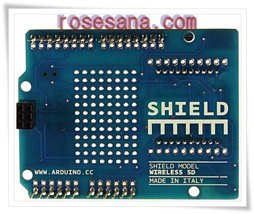
Arduino Wireless SD Shield

The Wireless SD shield allows an Arduino board to communicate wirelessly using a wireless module. It is based on the Xbee modules from Digi, but can use any module with the same footprint. The module can communicate up to 100 feet indoors or 300 feet outdoors (with line-of-sight). It can be used as a serial/usb replacement or you can put it into a command mode and configure it for a variety of broadcast and mesh networking options. The shields breaks out each of the Xbee's pins to a through-hole solder pad.

Included on board is a SD card slot. When using the SD Library to access the card, Pin 4 is CS and cannot be used otherwise. SPI also relies on pins 11, 12, and 13 for communication.

An on-board switch allows the wireless module to communicate with the USB-to-serial converter or with the microntroller.

The Arduino Pro

The Arduino Pro is a microcontroller board based on the ATmega168 (datasheet) or ATmega328 (datasheet). The Pro comes in both 3.3V / 8 MHz and 5V / 16 MHz versions. It has 14 digital input/output pins (of which 6 can be used as PWM outputs), 6 analog inputs, a battery power jack, a power switch, a reset button, and holes for mounting a power jack, an ICSP header, and pin headers. A six pin header can be connected to an FTDI cable or Sparkfun breakout board to provide USB power and communication to the board.

The Arduino Pro is intended for semi-permanent installation in objects or exhibitions. The board comes without pre-mounted headers, allowing the use of various types of connectors or direct soldering of wires. The pin layout is compatible with Arduino shields. The 3.3V versions of the Pro can be powered with a battery.

Summary
  • Microcontroller ATmega168 or ATmega328
  • Operating Voltage 3.3V or 5V
  • Input Voltage 3.35 -12 V (3.3V versions) or 5 - 12 V (5V versions)
  • Digital I/O Pins 14 (of which 6 provide PWM output)
  • Analog Input Pins 6
  • DC Current per I/O Pin 40 mA
  • Flash Memory 16 KB (ATmega168) or 32KB (ATmega328) of which 2 KB used by bootloader
  • SRAM 1 KB (ATmega168) or 2 KB (ATmega328)
  • EEPROM 512 bytes (ATmega168) or 1 KB (ATmega328)
  • Clock Speed 8 MHz (3.3V versions) or 16 MHz (5V versions)

Rabu, 25 Juli 2012

Analog Sound Sensor

This small breakout board couples a small electret microphone with a 100x opamp to amplify the sounds of voice, door knocks, etc loud enough to be picked up by a microcontroller's Analog to Digital converter.
Pin Definition

The definition of sound sensor pin is
Signal Output
GND
Power

Selasa, 24 Juli 2012

Arduino Wireless SD shield

As the name implies, the Arduino Wireless SD shield serves two functions. Foremost, this shield allows you to easily interface with Xbee transceiver modules to create mesh networks, and other wireless devices. Secondly, the micro SD socket allows you to store and access a large amount of data. Whether using these functions by on their own or together, this chip greatly enhances the capabilities of a standard Arduino.

The Wireless SD shield allows an Arduino board to communicate wirelessly using a wireless module. It is based on the Xbee modules from Digi, but can use any module with the same footprint. The module can communicate up to 100 feet indoors or 300 feet outdoors (with line-of-sight). It can be used as a serial/usb replacement or you can put it into a command mode and configure it for a variety of broadcast and mesh networking options. The shields breaks out each of the Xbee's pins to a through-hole solder pad.

Included on board is a SD card slot. When using the SD Library to access the card, Pin 4 is CS and cannot be used otherwise. SPI also relies on pins 11, 12, and 13 for communication.
An on-board switch allows the wireless module to communicate with the USB-to-serial converter or with the microntroller.

The Arduino Pro

The Arduino Pro is a microcontroller board based on the ATmega168 (datasheet) or ATmega328 (datasheet). The Pro comes in both 3.3V / 8 MHz and 5V / 16 MHz versions. It has 14 digital input/output pins (of which 6 can be used as PWM outputs), 6 analog inputs, a battery power jack, a power switch, a reset button, and holes for mounting a power jack, an ICSP header, and pin headers. A six pin header can be connected to an FTDI cable or Sparkfun breakout board to provide USB power and communication to the board.
The Arduino Pro is intended for semi-permanent installation in objects or exhibitions. The board comes without pre-mounted headers, allowing the use of various types of connectors or direct soldering of wires. The pin layout is compatible with Arduino shields. The 3.3V versions of the Pro can be powered with a battery.
The Arduino Pro was designed and manufactured by SparkFun Electronics.

Summary
  • Microcontroller ATmega168 or ATmega328
  • Operating Voltage 3.3V or 5V
  • Input Voltage 3.35 -12 V (3.3V versions) or 5 - 12 V (5V versions)
  • Digital I/O Pins 14 (of which 6 provide PWM output)
  • Analog Input Pins 6
  • DC Current per I/O Pin 40 mA
  • Flash Memory 16 KB (ATmega168) or 32KB (ATmega328) of which 2 KB used by bootloader
  • SRAM 1 KB (ATmega168) or 2 KB (ATmega328)
  • EEPROM 512 bytes (ATmega168) or 1 KB (ATmega328)
  • Clock Speed 8 MHz (3.3V versions) or 16 MHz (5V versions)
  • Power
  • The Arduino Pro can be powered via the USB header, with a battery, or with an external power supply. The battery power jack is a JST header. A power jack for an external supply can be soldered to the board.

The Arduino Leonardo

The Arduino Leonardo is a microcontroller board based on the ATmega32u4 . It has 20 digital input/output pins (of which 7 can be used as PWM outputs and 12 as analog inputs), a 16 MHz crystal oscillator, a micro USB connection, a power jack, an ICSP header, and a reset button. It contains everything needed to support the microcontroller; simply connect it to a computer with a USB cable or power it with a AC-to-DC adapter or battery to get started.

The Leonardo differs from all preceding boards in that the ATmega32u4 has built-in USB communication, eliminating the need for a secondary processor. This allows the Leonardo to appear to a connected computer as a mouse and keyboard, in addition to a virtual (CDC) serial / COM port. It also has other implications for the behavior of the board; these are detailed on the getting started page.

Summary
  • Microcontroller ATmega32u4
  • Operating Voltage 5V
  • Input Voltage (recommended) 7-12V
  • Input Voltage (limits) 6-20V
  • Digital I/O Pins 20
  • PWM Channels 7
  • Analog Input Channels 12
  • DC Current per I/O Pin 40 mA
  • DC Current for 3.3V Pin 50 mA
  • Flash Memory 32 KB (ATmega32u4) of which 4 KB used by bootloader
  • SRAM 2.5 KB (ATmega32u4)
  • EEPROM 1 KB (ATmega32u4)
  • Clock Speed 16 MHz

Arduino Uno - R3

The new Arduino Uno R3. In addition to all the features of the previous board, the Uno now uses an ATmega16U2 instead of the 8U2 found on the Uno (or the FTDI found on previous generations). This allows for faster transfer rates and more memory. No drivers needed for Linux or Mac (inf file for Windows is needed and included in the Arduino IDE), and the ability to have the Uno show up as a keyboard, mouse, joystick, etc.

The Uno R3 also adds SDA and SCL pins next to the AREF. In addition, there are two new pins placed near the RESET pin. One is the IOREF that allow the shields to adapt to the voltage provided from the board. The other is a not connected and is reserved for future purposes. The Uno R3 works with all existing shields but can adapt to new shields which use these additional pins.

Arduino is an open-source physical computing platform based on a simple i/o board and a development environment that implements the Processing/Wiring language. Arduino can be used to develop stand-alone interactive objects or can be connected to software on your computer (e.g. Flash, Processing, MaxMSP). The open-source IDE can be downloaded for free (currently for Mac OS X, Windows, and Linux).

Note: The Arduino Uno R3 requires the Arduino 1.0 drivers folder in order to install properly on some computers. We have tested and confirmed that the R3 can be programmed in older versions of the IDE. However, the first time using the R3 on a new computer, you will need to have Arduino 1.0 installed on that machine. If you are interested in reading more about the changes to the IDE, check out the official Arduino 1.0 Release notes!

Features:

  • ATmega328 microcontroller
  • Input voltage - 7-12V
  • 14 Digital I/O Pins (6 PWM outputs)
  • 6 Analog Inputs
  • 32k Flash Memory
  • 16Mhz Clock Speed

Kamis, 19 Juli 2012

DFRduino Mega 1280 (Arduino Mega 1280 Compatible)

The DFRobot DFRduino ATMega1280 MEGA USB Microcontroller is a microcontroller board based on the ATmega1280 integrated circuit. It 00% same as the original Arduino Mega.It has 54 digital input/output pins (of which 14 can be used as PWM outputs), 16 analog inputs, 4 UARTs (hardware serial ports), a 16 MHz crystal oscillator, a USB connection, a power jack, an ICSP header and a reset button. It contains everything needed to support the microcontroller; simply connect it to a computer with a USB cable or power it with an AC-to-DC adapter or battery to get started. The Mega is compatible with most shields designed for the Arduino Duemilanove or Diecimila. The DFRobot ATMega1280 MEGA USB Microcontroller can be powered via the USB connection or with an external power supply. The power source is selected automatically. External (non-USB) power can come either from an AC-to-DC adapter (wall-wart) or battery. The adapter can be connected by plugging a 2.1mm center-positive plug into the board's power jack. Leads from a battery can be inserted in the Gnd and Vin pin headers of the POWER connector. This board is almost identical to the Arduino MEGA with the exception of the color of the PCB.

Specifications
  • Microcontroller ATmega1280
  • Operating Voltage 5V
  • Input Voltage (recommended) 7-12V
  • Input Voltage (limits) 6-20V
  • Digital I/O Pins 54 (of which 14 provide PWM output)
  • Analog Input Pins 16
  • DC Current per I/O Pin 40 mA
  • DC Current for 3.3V Pin 50 mA
  • Flash Memory 128 KB of which 4 KB used by bootloader
  • SRAM 8 KB
  • EEPROM 4 KB
  • Clock Speed 16 MHz


Shield Compatibility

The Mega is designed to be compatible with most shields designed for the Diecimila or Duemilanove. Digital pins 0 to 13 (and the adjacent AREF and GND pins), analog inputs 0 to 5, the power header, and ICSP header are all in equivalent locations. Further the main UART (serial port) is located on the same pins (0 and 1), as are external interrupts 0 and 1 (pins 2 and 3 respectively). SPI is available through the ICSP header on both the Mega and Duemilanove / Diecimila. Please note that I2C is not located on the same pins on the Mega (20 and 21) as the Duemilanove / Diecimila (analog inputs 4 and 5).

The Mega is compatible with
  • Arduino Mega Prototype Shield
  • Arduino I/O Shield
  • Arduino LCD Shield
  • Arduino Motor Shield

The Mega is NOT compatible with 'Arduino Ethernet Shield'